Excerpt from H. Ott 'Noise Reduction Techniques in Electronic Systems': '... a balanced circuit is a 2-conductor circuit in which both conductors and all circuits connected to them have the same impedance with respect to ground and to all other conductors. The purpose of balancing is to make the noise pickup equal in both conductors, in which case it will be a common-mode signal that can be made to cancel out in the load...'
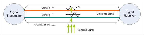
The two conductors of a balanced line operate in a push-pull manner. As the voltage in one conductor becomes positive, the voltage in the other conductor becomes negative (both by the same amount and at the same time). Both conductors are equal in voltage but opposite in polarity. The receiving circuit for a balanced signal is called a differential amplifier.
The wanted audio signal itself is opposite in polarity in both conductors, the effect in the differential amplifier is that this signal is processed by the differential amplifier. Any unwanted electrical interference will interact with both conductors the same and also with the same polarity. The same polarity voltages aren't processed in the differential amplifier and the unwanted signal, the interference, is cancelled out. The unwanted voltage is a common-mode voltage, it is common to both inputs of the differential amplifier.
See Common Mode Voltage / Common Mode Rejection.
Noise immunity on balanced audio lines is completely dependant on how WELL the input and output impedances are balanced and on the common mode rejection ratio of the audio input.
The shield on regular balanced lines is only an additional protection against interference, but it is actually not a substantial part of the balanced line. Balanced lines without shield work very well too. Especially the number of twists between the two conductors are more important. Twisted pair cable (CAT5/6/7) can be used with very good results for balanced audio lines.
The definition which of the two conductors is 'positive' and which is 'negative' is a pure definition to ensure the proper polarity of the signal throughout a device or a system, it is not a part of the definition of a balanced line. Using a device from input to output in the 'opposite' polarity as labelled (+ for - and - for +), wouldn't degrade the signal in any way. The definition of the polarity of connections and connectors (like the XLR connector) is necessary to create systems with a defined polarity but is not essential to the characteristics of a balanced line! The only needed definition for a balanced line is to have input and output in the SAME polarity.