
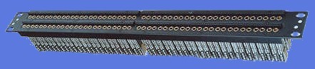
The most common types of analog audio patchbay connectors are the 1/4" phone plug, called 'Longframe' and the 11/64" Bantam or TT (Tiny Telephone) plug. The Longframe patchbay has normally 24 jacks per row and the Bantam patchbay has 48 jacks per row.

|
|
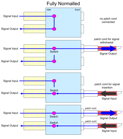
| half normalled audio patchbay | fully normalled audio patchbay |


To keep ground-loop hum under control, it is necessary to choose one uniform method of
interconnecting the grounds / shields of the audio equipment, connected to the audio patchbay.
The typical four types of grounding patchbays are:
ST (Shields Terminated): the shields of each wire are terminated only at the jack terminal. Shield wires do not interconnect from jack to jack
SB (Shields Bussed): each row of jacks has a bus bar that connects all shields
from that row, one single ground-wire connects these shields to ground
SS (Shields Strapped): the shield of each top row output jack is connected to the shield of the designated input jack below it, the connection is not interrupted, whether or not patch cables are inserted into the jacks
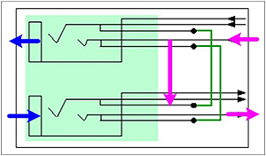
SN (Shields Normalled): switch contacts normal the shield in the same way as the signal wired are normalled, these contacts allow the shield to be half or full normalled