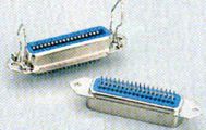
The Centronics Interface Connector is a standard printer connector. It uses a 36 pins amphenol connector.
The printer is equipped with the female connector.
| |
| Pin | Abbreviation | Signal / Function |
| 1 | STROBE | - Strobe (active low to read data) |
| 2 | DATA 1 | - data line 1 |
| 3 | DATA 2 | - data line 2 |
| 4 | DATA 3 | - data line 3 |
| 5 | DATA 4 | - data line 4 |
| 6 | DATA 5 | - data line 5 |
| 7 | DATA 6 | - data line 6 |
| 8 | DATA 7 | - data line 7 |
| 9 | DATA 8 | - data line 8 |
| 10 | ACKNLG | - Acknowledge (pulsed low to indicate that data has been received) |
| 11 | BUSY | - Busy (taken high under the following conditions: (a) during data entry (b) during printing operation (c) when printer is OFF-LINE (d) during print error status) |
| 12 | PE | - Paper end (taken high to indicate that the printer is out of paper) |
| 13 | SLCT | - Select (taken high to indicate that the printer is in the selected state) |
| 14 | AUTO FEED XT | - Automatic feed (when this input is taken low, the printer is instructed to produce an automatic line feed after printing. This function can be selected internally by means of a DIP switch) |
| 15 | n.c. | - Not connected (unused) |
| 16 | 0V | - Logic ground |
| 17 | CHASSIS GND | - Printer chassis (normally isolated from logic ground at the printer) |
| 18 | n.c. | - Not connected (unused) |
| 19-30 | GND | - Signal ground (originally defined as 'twisted pair earth returns' for pin numbers 1 to 12 inclusive) |
| 31 | INIT | - Initialize (this line is pulsed low to reset the printer controller) |
| 32 | ERROR | - Error (taken low by the printer to indicate: (a) PAPER END state (b) OFF-LINE state (c) error state) |
| 33 | GND | - Signal ground |
| 34 | n.c. | - Not connected (unused) |
| 35 | LOGIC 1 | - Logic 1 (usually pulled high via 3.3 kohm) |
| 36 | SLCT IN | - Select input (data entry to printer is only possible when this line is taken low, but this function may beł disabled by means of an internal DIP switch) |